Delivery Box Assembly
Designed a snap-fit delivery box subsystem for an aerial delivery drone, including 7 fully modeled parts, dimensioned engineering drawings, and a rod-actuated lid closure mechanism to secure liquid cargo during flight.
Subsystem Owner (Delivery Box) · Fall 2024 · Team of 5
Contributions
Designed a parametric delivery box subsystem integrating cargo containment, rod-actuated lid closure, and keypad access control
▾Result
A complete parametric CAD assembly with 7 individually drawn parts, a BOM, and an assembly instruction package was completed and passed team review and course submission.
Designed a rod-actuated snap-fit lid mechanism to prevent liquid cargo from tipping and spilling during aerial movement
▾Result
The snap fit design passed CAD assembly mate checks, and the assembly instructions validated the engagement sequence with visual confirmation at each step.
Interfaces
| From | To | Type | Description |
|---|---|---|---|
| Box lid | Box base | mechanical | The lid (18.00" × 10.00") rests over the open top of the box by gravity. Cutouts on the lid perimeter align with the rod slots on the box wall top edges so the lid sits flush on the rim without interfering with rod insertion. The rod then sits across the top of the lid, holding it in place. |
| Delivery Box | Rod and Snap Fit | mechanical | The rod (Ø1.00" shaft) passes through the lid slots and engages the snap fit clip (R.51" snap radius, 0.01" diametric clearance). The rod groove is located at 0.75" from the snap fit engagement face to ensure full seating before the clip locks. |
| Delivery Box | Leg Assembly | mechanical | Each leg grips the rod passing through the 4× Ø1.02" holes in the box walls. The leg is captured laterally between the dumbbell-shaped rod extrude on one side and the snap fit clip on the other, preventing the box from sliding along the rod during flight. |
Documents

Delivery box item 5 in system context
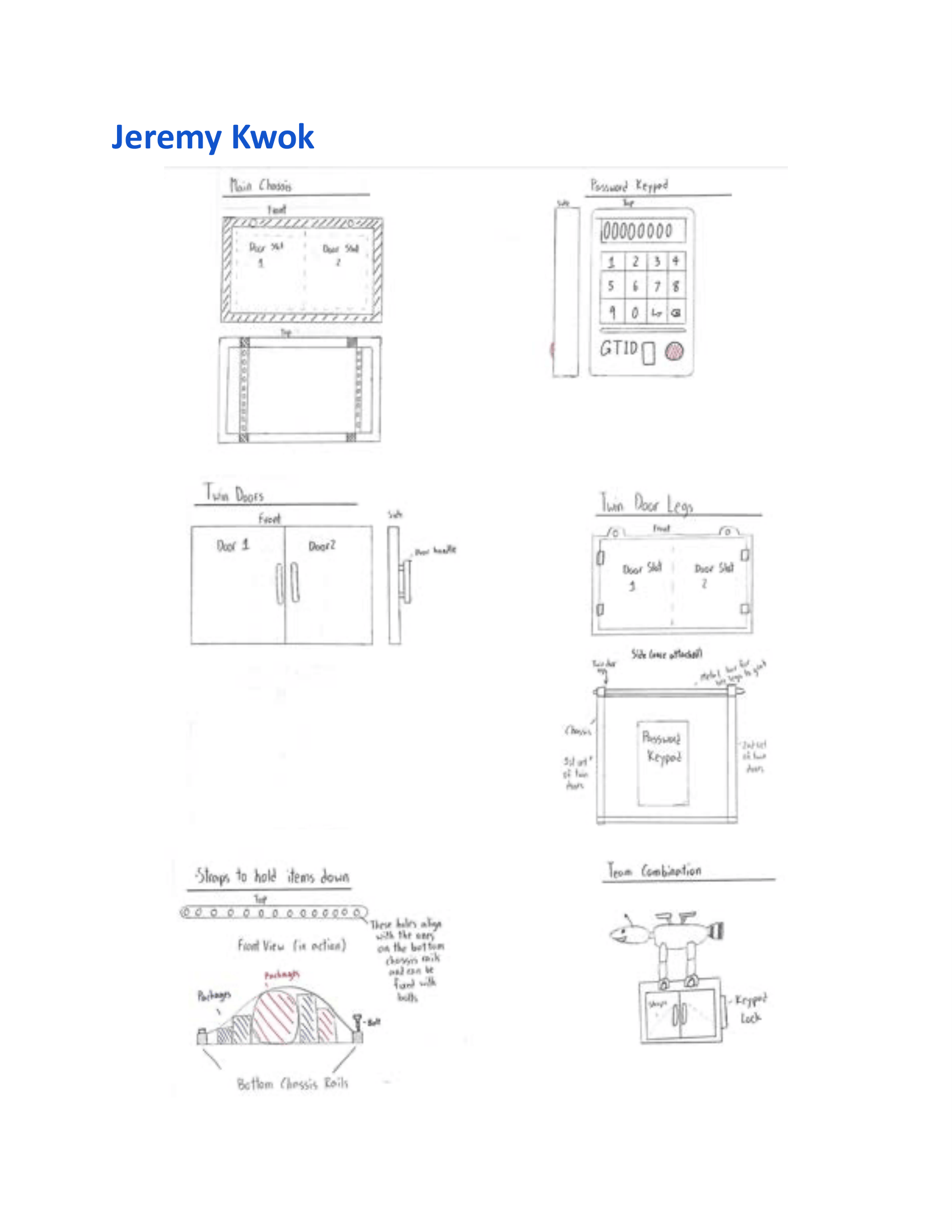
Early-stage design sketch exploring subsystem layout, door mechanism, and keypad placement prior to CAD modeling.
Limitations
- • The entire subsystem was designed and verified through CAD assembly checks only. No physical prototype was built, so fit, weight, and structural behavior under real loading conditions remain unvalidated.
- • The subsystem dimensions were coordinated with teammates through verbal agreement and shared SolidWorks files rather than a formal interface specification document, which introduced integration risk — as seen during assembly when leg-to-box dimensioning required rework by the legs subteam.
Lessons & Next Steps
- • Establishing formal dimensional agreements at subsystem interfaces before CAD modeling begins would have reduced the integration issues encountered during full assembly. Verbal coordination works for simple projects but breaks down as part count and interface complexity grow.
- • Snap fit and rod-actuated closure mechanisms are a practical alternative to hinges in assemblies where tool-free access and lateral retention matter. However, snap fit geometry must be designed in conjunction with material selection — sizing the profile and chamfer angle without a deflection analysis for a specific material leaves the design incomplete. A geometry that works in ABS may fracture in aluminum.
- • Engineering drawings follow strict conventions for how dimensions are arranged, stacked, and referenced that are not enforced by CAD modeling alone. Learning to produce fully dimensioned drawings to ME1670 standards, including correct view selection and dimension placement, made the design intent legible to teammates and reviewers without requiring access to the SolidWorks model.